Reverse Engineering
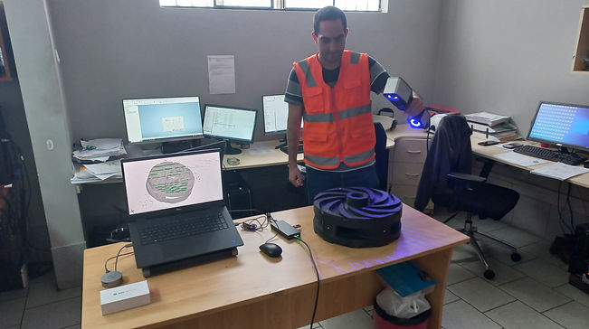
During my first months at this company, I underwent a reverse engineering training using the ZEISS Quality Suite software from GOM Metrology. This course focused on operating a three-dimensional scanner and utilizing the GOM Inspect program for measurements, polygonization, and mesh-work.
Subsequently, after exporting the mesh in STL format, it was imported into the ZEISS Reverse Engineering software, which converted the point cloud into a CAD file. With this file, the corresponding drawings or analysis were generated.
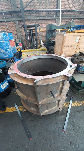
Project: Vacuum Pump Casing - 6000cfm
This project arises from the need to update the existing part drawing of the 6000cfm vacuum pump casing, as it was outdated. Due to its large size, it required thorough preparation and the use of Satellite Mode, which employs photogrammetry to capture images from various angles, enabling precise three-dimensional reconstruction even on large objects like this.
It all begins with the preparation of the part, positioning the self-reflective markers that work with the scanner to capture the 3D image. Additionally, the called Hyperscales are placed to aid photogrammetry. With this setup, the entire component is scanned.
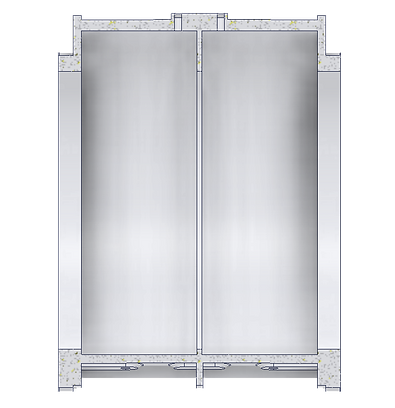
Once the part is scanned, the result obtained in GOM Inspect is the following mesh:
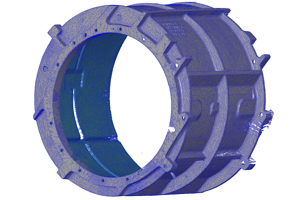
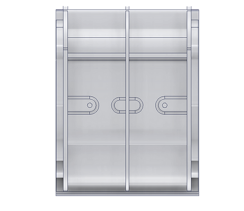
As you can notice, the mesh has some imperfections that can be refined within the GOM Inspect software itself. Once the mesh is reconstructed, it is exported to STL and transferred to the ZEISS Reverse Engineering software. It's not necessary to have all the points of a part to achieve an effective reconstruction. The reconstruction is carried out by defining a coordinate origin and deriving geometries from it.


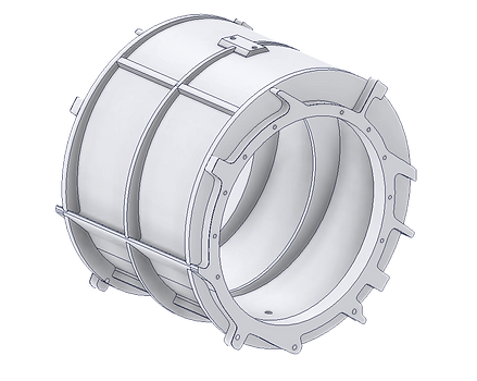
Once a solid is obtained, it is exported in STEP format (an interchangeable CAD file) and taken to CAD-CAE software for its corresponding modification, analysis, simulation, rendering, or detailing. This concludes the reverse engineering process.

Project: Vacuum Pump Head -1000cfm
The same process was carried out with the 1000cfm pump head, a highly complex piece. The following photos illustrate the preparation and scanning process, as well as the final assembly of the machine.


Office Projects
The previous projects were carried out on-site. However, for pieces with a maximum dimension of less than 1 meter, the process was moved to the office. Here are various photos showing different scanning processes.